NOTE FROM AUTHOR [2024/05/07]: This post was originally written in 2022, but sat unpublished. I used this keyboard on and off for about 2 years. I still like the layout of the Kinesis better, but I can use either fluently. I’ve had to do a few repairs on it. On the righthand half, the pro micro controller’s USB port broke so I ended up replacing the controllers with Elite-Cs and addressing all the poor soldering.
I still love the Kinesis, but appreciate that the thumb cluster on the dactyl was a bit closer, but was really annoyed with the stagger of the outermost columns. After building the dactyl (lightcycle) below, I upgraded the original kinesis with the Stapelberg mod. It’s 2024 now and I actually alternate between a handwired Dactyl-cc with 67g, un-lubed, Zealio® V2 Switches and “like-new” Kinesis Advantage 1 (in black) with a Stapelberg mod PCB. My original kinesis is at my parent’s home at a hotdesk where my brothers and I work from time to time. Admittedly, I would probably not have built the Dactyl-cc had I chosen better switches that the Kailh box browns below.
I’m a huge fan of my Kinesis Contour. I wrote a series of articles (first, second and third) about it. I was able to get the first up and running shortly before the pandemic set in and actually swapped in the old PS/2 controller with an Advantage 1 controller board. I have been using it ever since. It has ruined me for all other keyboards.
At the time, I was expecting to be returning to the office in 2021 and I considered the implications of having to potentially move the Kinesis back and forth between my home office and Nulogy HQ downtown. I was not looking forward to that. This brought me to explore other more portable keyboard designs and I ended up purchasing an ErgoDash kit from Keycapsss.com. I never got around to building it though as it soon became apparent that our return to the office wasn’t in the cards.
Fast forward to Black Friday 2021, and I make the impulse decision to buy a 3D printer.
So I wanted to write my build log for this project. Much of the resources I cite deal directly with the Dactyl (lightcycle) and/or Dactyl Manuform variants.
Equipment:
It’s important to note that I choose to build the Dactyl using TWO Pro Micro controllers.
Tools that you will need:
- Soldering Iron
- Solder
- Flush Cutter
- X-acto knife
- Tweezers
- Soldering Wick
- soldering flux
- Soldering vaccuum
- Multimeter
- Needle nose pliers
I had most of this equipment already purchased from STEM projects that my kids were doing. Admittedly, I want to get a better soldering iron.
Materials that I used:
- Kailh Box Brown switches x 70
- I chose box browns because I wanted a similar feel to the vintage Cherry MX Brown switches in my Kinesis. They are cheaper than the original Cherry MX
- 1N4148 diodes x 70
- I had this from my Ergodash kit. I ended up buying a 500-pack from Digikey.
- Pro Micro controller x 2
- These are the brains for each side of the keyboard. I ended having to buy more because they are very fragile and I know just enough to be dangerous.
- TRRS cable x 1
- I had a 4-pin TRRS cable. You require 3 of the 4-pins. Make sure you get 3.5mm cables with 3 stripes on either side.
- TRRS jacks x 2
- There are fat and slim TRRS jacks. Most newer designs use the slim version. I ended up relocating the TRRS jack because i couldn’t get it to fit inside the case.
- 30cm USB C Female to Micro B Male panel mount cable x 2
- I bought these to protect the Pro Micro controllers as the ports are notoriously fragile. I am migrating to USB C cables across the board, so I chose an adapter, but these proved to be problematic with the case as they are 30 cm in length.
- If i had to do it again, I would use this 15 cm Micro B to Micro B panel mount cable instead and just hope that reinforcing the micro USB ports will do.
- Gel wrist rests x 2
- These gel rests can be printed combined with the extended base or separately.
- #6-32 machine screws
- #6-32 square nuts
- Tactile switches x 2
- For the reset button.
- Coloured solid core 22 gauge wire
- OPTIONAL: 28 AWG Magnet wire
- You can make do using 22 gauge wire, but I’ve read that using magnet wire makes for an easier job for wiring the columns.
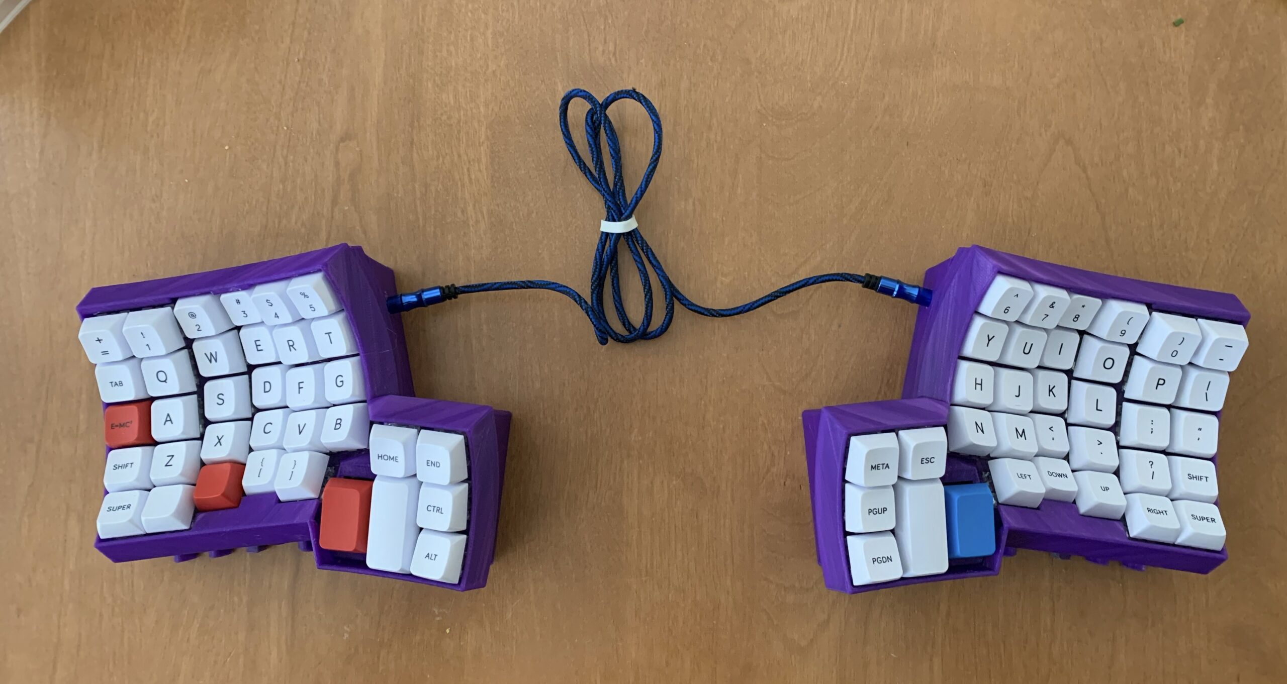
- MelGeek MDA Ortholinear Keycap set
- I am considering picking up 4 DSA blanks for the larger thumb cluster buttons.
The case
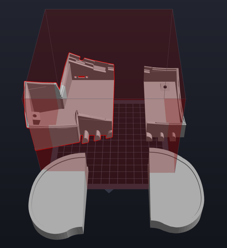
I download a pre-rendered, ready-to-print model: It is available on Thingiverse. I tried the original bottom case, but I gave up trying to fit everything into it. If you want to read a great story about the struggles of fitting everything into the stock base plate read Joe Devivo’s build log on his Dactyl keyboard. So I ended up using this extended base with wrist rests to better mirror the experience typing on a Kinesis Advantage. This clamshell approach encases all the components into two halves. The top half containing the keys and the bottom half containing your I/O ports. I’m not a fan of this approach as the two halves are wired together and it makes it much harder to work with. The 30 cm panel mount cable barely fits and you need to manage your wiring quite aggressively in order to fit everything together.
Printing
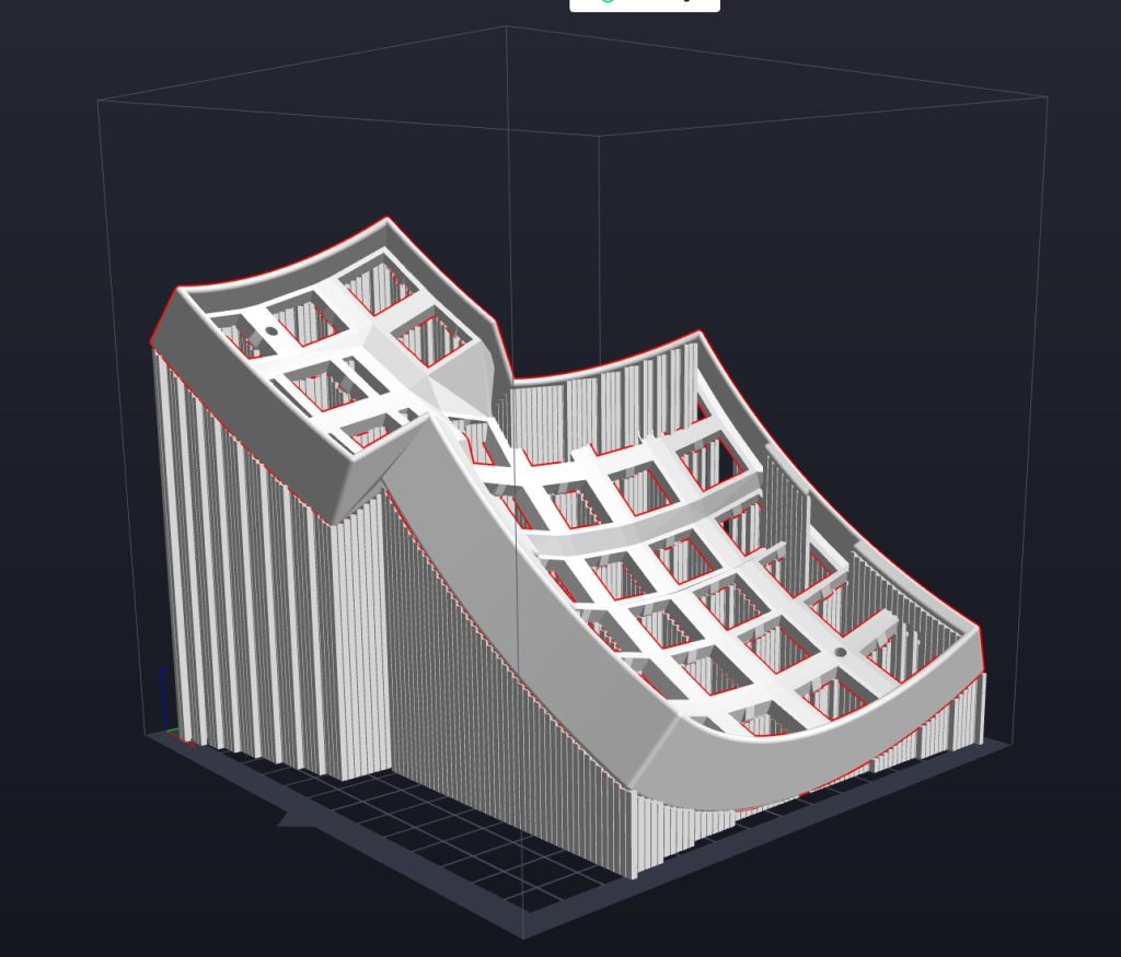
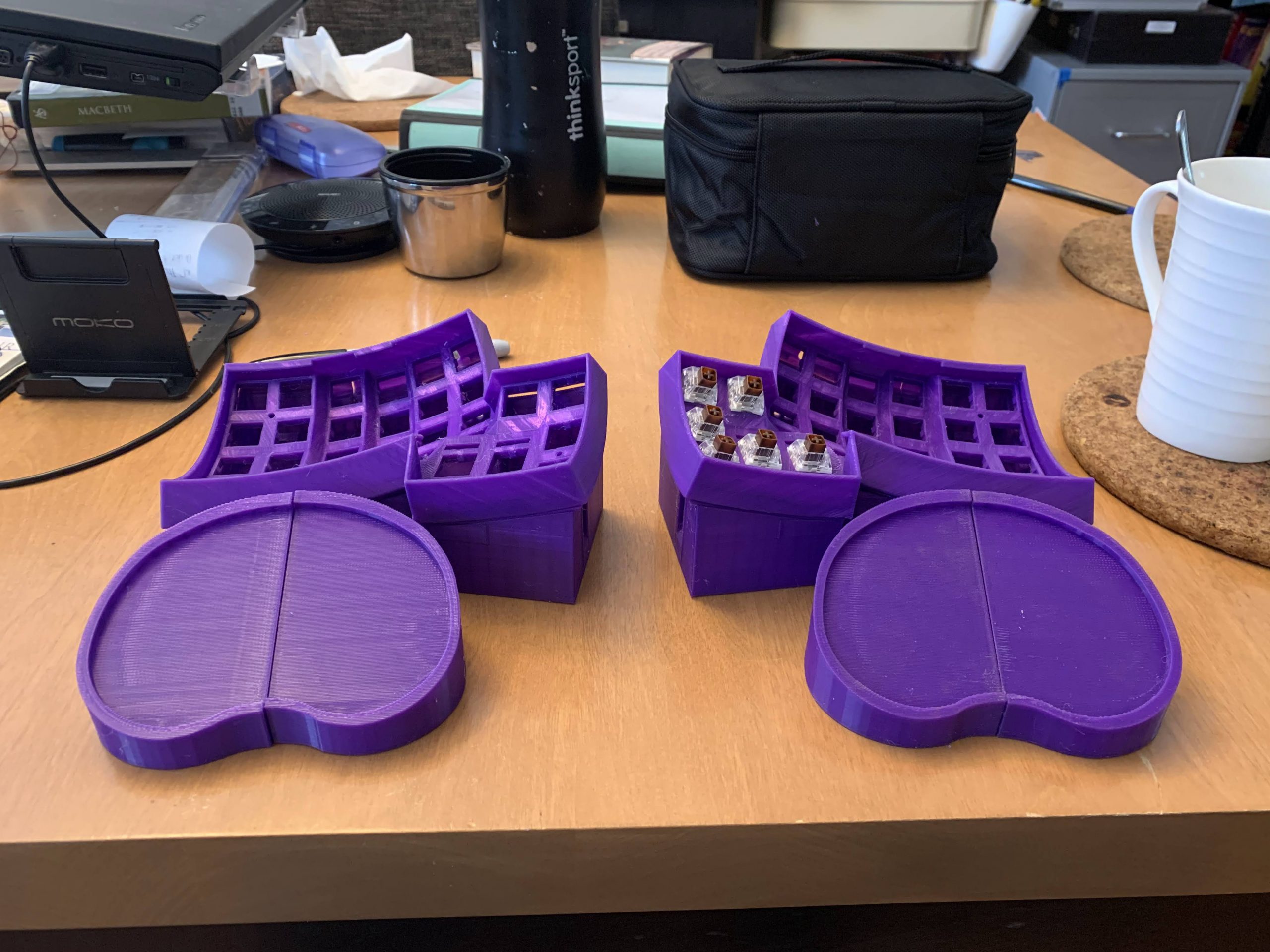
If you have a friend with a printer, I would encourage you to ask a favour to print out the keyboard case. Try to print it out in one piece, if possible. My bases are printed out in multiple pieces (4 each) and I’m not really happy with the results. In order to print faceplate, I had to set up a very aggressive angle on my printer and use a generous amount of supports. This is a waste of material and I ended up using an entire 1 kg roll of PLA filament. It also affects the structural integrity of the keyboard where expansion caused by the keycaps could rupture the casing along the angled PLA layers.
I glued the parts together using JB Weld, but decided to not do any extensive filling, sanding and painting.


Wiring
There are several great posts online that shows approaches to wiring the Keyboard matrix. Some are even Dactyl and DacMan specific.
- @cribbet’s “A modern wiring guide for keyboards” [geekhack.org]
- I used this approach. I may try magnet wire next.
- Sasha Solomon’s “Building my first keyboard (and you can too)” [medium.com]
- Dan Wilkerson’s “Building A Keyboard – My Dactyl Build Journal” [danwilkerson.com]
- Matt Adareth’s original dactyl guide [gihtub.com]
- @abstracthat’s Dactyl Manuform guide [github.com]
I was inspired a lot by Sasha Solomon’s guide and used her wiring layout for my boards. Her hand drawn diagrams are beautiful and very clear. It’s really approachable as well.
However, they DO NOT MATCH the wiring required for the handwired/dactyl-promicro build in the qmk repository which states, somewhat cryptically I might add, that:
Wiring is a 6×6 Matrix like the Dactyl Manuform
Dactyl with Arduino Pro Micro page in the QMK repository
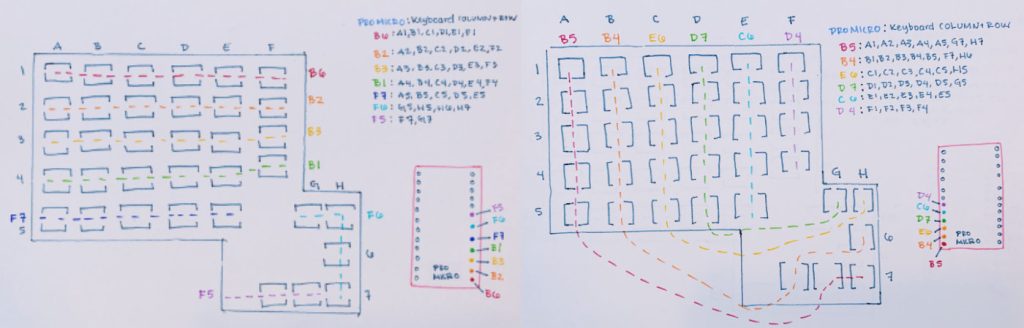
Sasha’s wiring diagram uses 7×6 setup and I didn’t feel like futzing around in the software and remapping the keymap.
For a Dactyl keyboard using two pro micros, the wiring diagram looks like this:
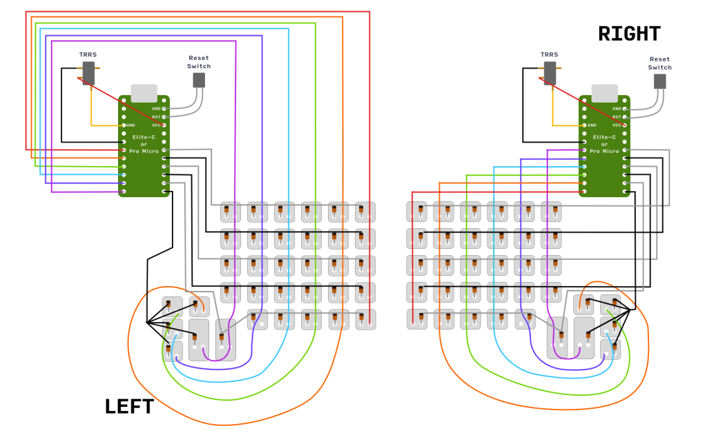
The key part is that the first and second buttons in the thumb cluster is treated as part of the first column.
I had a lot of excess wire from the leads that wasn’t necessary for the build, but helpful when I breadboarded the system for testing.


Prepare and Reinforce the Controllers
Pro Micros are notoriously fragile. There isn’t a lot of solder holding the port down to the PCB. The first thing I did was reinforce the port with solder and super glue.

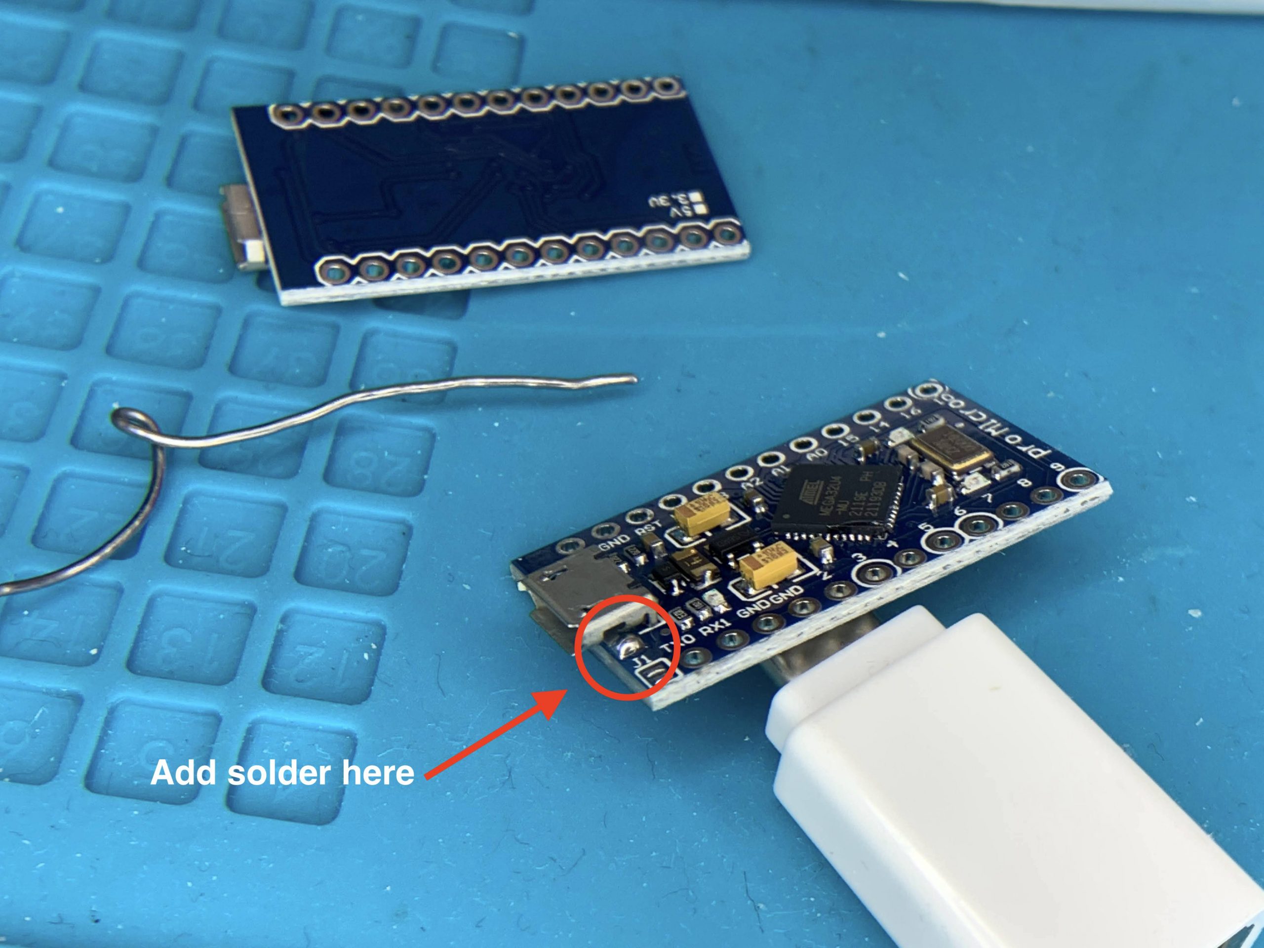

Do this for both pro micros.
I chose to put pin headers onto the bottom of the board (necessary for breadboarding) (or you can choose to socket your controller using Mil Max pins or diode legs). Regardless, this is good practice. It provides a surface to attach your wires and helps prevent you from damaging the circuit board with the soldering iron. Diode legs make great pins for socketing.
Flash the controllers
Follow the QMK firmware instructions for setting up your environment and toolchain.
Create you keymap using the handwired/dactyl-promicro folder:
qmk new-keymap -kb handwired/dactyl_promicro -km <keymap_name>
and build your firmware using the handwired/dactyl-promicro:
qmk compile -kb handwired/dactyl_promicro -km <keymap_name>
Use QMK Toolkit (Windows and Mac Only)